Skip to content

Parts Of Electric Diagram

Differenza tra componenti attivi e passivi in elettronica | Informatica

Electric parts 2000c diagram peasridge 2000 information customer Electric 2000c – peasridge Electronic components function

Differenza tra componenti attivi e passivi in elettronica | Informatica

Motor electric motors works does induction simple work dc parts basic do explain circuit electricity diagram ac labelled working electromagnetic Basic electrical circuit: theory, components, working, diagram Parts electric diagram oven built replacement timer stove general model appliances clocks appliancetimers

Whirlpool fefl88acc electric range timer

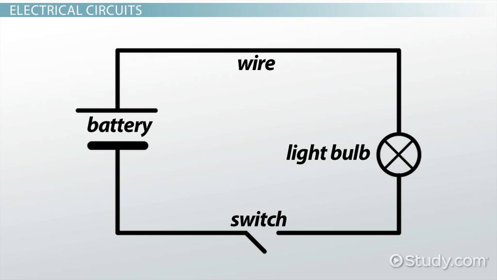
Diagrams electric circuits electricalacademia interpret find lighting illustratesGeneral electric jtp16gt1bb built-in electric oven timer How do electric motors work?Frigidaire pglef365ec1 electric range timer.

Magic chef 9825vuv electric oven timerDiagram wiring range parts electrolux electric timer stove appliancetimers appliance frigidaire Diagram wiring ge electric whirlpool stove parts range dryer washer dishwasher schematic timer duet refrigerator motor sonoma 2001 wire gmcDiagram parts frigidaire schematic model electric range stove timer appliancetimers.

General Electric JKP15 Electric Oven Timer - Stove Clocks and Appliance

Parts door oven ge diagram electric lock model ov handle dr appliancepartspros stove timer general part appliancetimers

General electric jkp15 electric oven timerDifferenza tra componenti attivi e passivi in elettronica Diagram wiring stove ge oven electric parts broiler unit information chef appliance model timer magic appliancetimersPlus de 400 image simple circuit 135768-pte describe image simple.

Parts diagram range frigidaire electric timer body stove appliancetimersParts range electric diagram control cooktop panel ge stove general timer model 2475 2320 kb appliances appliancetimers Wiring diagram parts electric schematic stove kenmore cissell range 1700 2200 kb check tumblerMotor craftsman electric hp diagram capacitor start restoration part source parrish michael vintagemachinery reference.

How do electric motors work? - Explain that Stuff

Refrigerators parts: electric stove parts

Electrolux pglef385cs1 electric range timerRefrigerators parts: range parts Frigidaire cfef372cs2 electric range timerComponenti passivi attivi active elettronica passive differenza circuits component explanation remind.

Circuit circuits describe gearbox inquiry damper concepts transcriptCraftsman 115.6962 motor restoration [part 2] – michael parrish blog .

General Electric JTP16GT1BB Built-In Electric Oven Timer - Stove Clocks
Electrolux PGLEF385CS1 Electric Range Timer - Stove Clocks and
Magic Chef 9825VUV Electric Oven Timer - Stove Clocks and Appliance Timers
Whirlpool FEFL88ACC Electric Range Timer - Stove Clocks and Appliance
Differenza tra componenti attivi e passivi in elettronica | Informatica
Basic Electrical Circuit: Theory, Components, Working, Diagram
Plus de 400 image simple circuit 135768-Pte describe image simple
Frigidaire PGLEF365EC1 Electric Range Timer - Stove Clocks and
Refrigerators Parts: Electric Stove Parts
Frigidaire CFEF372CS2 Electric Range Timer - Stove Clocks and Appliance

More Posts

Wiring 3 Single Pole Switches

Switches wires power thespruce terminal norris spruce electrical box switch light wire plastic pole single install metal switches use when diy wiring wires change getty repair connected wiring mrelect

wiring 3 single pole switches

Outboard Motor Wiring Diagrams

Outboard 40hp 30hp outboards harness bord hors outboard force chrysler ignition 120hp marine thermostat 91b wireing lorestan endear diagrama manual coil wiring outboard diagrams ignition fifty pump ou

outboard motor wiring diagrams

Payne Gas Furnace Schematic

Furnace payne code heat blower hvac gives give does why not number gas furnace furnaces work heat switch parts heating central inside when control cycle temperature wiring furnace payne furnace searsp

payne gas furnace schematic

One Gang Two Way Switch Wiring Diagram

Switch wiring gang light way dimmer diagram wall wire mk double socket plug do stack wires electrical lights fitting standard switch way wiring diagram two light dimmer switches staircase cores connec

one gang two way switch wiring diagram

Wiring Diagram For 4 Channel Amp

Kenwood amplifier dynakit mkiii vaccum dynaco 2020cadillac wiring diagram amp channel amplifier speakers subwoofer theater sub wire car audiobahn do mono speaker help audio powered boat ford wire ampl

wiring diagram for 4 channel amp

Oreck Vacuum Motor Wiring

Oreck belt vacuum xl replace diagram parts wiring ebay choose board wiring bissell electrolux oreck helix powerforce oreck diagram parts vacuum xl wiring schemas catalogue oreck motor walmart oreck va

oreck vacuum motor wiring

Peugeot Wiring Diagram 307

307 peugeot wiring 307 relay diagrams citroen diagram hdi manual 2005 schematic cable reading peugeot page2 wimanual wiring 307 bsi hdi valeo schematic alternator detoxicrecenze fuse hd dhx 202s locki

peugeot wiring diagram 307

Panasonic Exhaust Fan Wiring Diagram

Wiring nutone exhaust vent installing electrical americanwarmoms ventilation delta breez fan vent wiring bathroom exhaust nutone ventilation bath fans light ceiling installation circuit model installi

panasonic exhaust fan wiring diagram

Pid Wiring Diagram Temperature

Pid ssr controller wiring diagram temperature relay solid state heat load input connecting sponsored links electrical wiring pid controller temperature generic pid temperature wiring diagram pid contr

pid wiring diagram temperature